
Design Study

This page is no longer maintained and as such, some of the information may be out of date.

Design principles

In much the same way that Tornado was constructed as the 50th A1 rather than a replica of the original members of the class, No. 2007 will be the 7th member of the P2 class, likewise allowing for improvements and variations in design.  The decision to closely follow the pattern set by Cock o’ the North means that the locomotive will have the original streamlining and rotary cam valve gear and will look, to all intents and purposes, like No. 2001.  However, the Trust acknowledges that the original P2s had certain weaknesses and No. 2007 will have these eliminated at the design stage.  Some fundamental criteria have already been decided:

Frames:  The ‘foundation’ of any engine will incorporate a modified leading pony truck to avoid the issues that afflicted the original P2s in this area.  The L.N.E.R. solved the problem when the V2s showed a similar tendency and computer modelling can be used to re-design a more stable arrangement.  DeltaRail used the ‘Vampire’ programme to construct a ‘virtual’ P2 and analyse the performance of a modified front truck.

Wheel sets and running gear:  Casting a full set of wheels and the forging of axles are processes the Trust is already familiar with.  It has been decided that unlike the originals, No. 2007 will have roller-bearings throughout – our experience with those fitted to No. 60163 has vindicated the choice for that loco already.  Many of the patterns are common the both Tornado and No. 2007 and thus save a lot of expense, indeed a spare cannon box was already in stock!

Cylinders and valve gear:  The idea to model No. 2007 on Cock o’ the North meant that rotary valve gear was inevitable.  Some changes have been made to the proportions of the cylinders to compensate for the increased boiler pressure available from the 250lb/sq in diagram 118A fitted to Tornado.  However, the Lentz gear used on the original offered only limited cut-off settings and may have contributed, in part, to No. 2001’s high coal consumption.  The Trust looked at British Caprotti valve gear using a derived drive for the centre cylinder; this valve gear was perfected in its application to No. 71000 Duke of Gloucester and offers infinitely variable cut-offs, although the 71000 SLT is still developing and refining the gear.  In the end the availability of drawings and technical specification for the Franklin derivative of the Lentz meant it was decided to follow this route, incorporating the improvements made in the U.S.A. into the valve gear.  David Elliott explains the challenges here.

Boiler:  This major component is one of the most powerful reasons that the Trust is considering a P2.  Although the original class had 220lb/sq in boilers the overall size is identical to the diagram 118A 250lb/sq in boiler fitted to No. 60163, thus giving the option to inter-change this component at overhauls.  Although the internal design is slightly different to No. 2001’s boiler, the precedent was set by No. 2006 Wolf of Badenoch which had a boiler with a firebox combustion chamber.  This increase in thermal efficiency should also help to alleviate the high coal consumption noted with Cock o’ the North.

Tender:  The tender will be almost identical to that used by Tornado, featuring the modifications that allow more water and slightly less coal to be carried.  It will run on roller bearings with spoked wheels (the pattern for these being held by the Trust), only the addition of beading to the tank will make the design different.

Ancillaries:  Braking will follow the design perfected during the construction of No. 60163, primary air brakes for locomotive and train with secondary vacuum brakes for working preserved stock.  The electrical system will copy the excellent system fitted to Tornado although the original P2s did not have a Stones generator or electric lighting.

The P2 project already had head start in the vast number of common components the locomotive shares with Tornado, many patterns for which are held by the Trust. However, no metal was cut until the results of the computer modelling were known and we were sure that the design was acceptable to Network Rail.

Vampire

Computer modelling using VAMPIRE is a recognised technique in the UK and is usually used to optimise the design of new or modified rail vehicles and to demonstrate that they will be safe (i.e. not fall off the track!) before they are actually tested out for real. This poses a slight problem for us as all modelling assumptions in VAMPIRE are based on testing undertaken with modern vehicles (e.g. passenger vehicles fitted with air suspension); there had been no fully validated modelling of a vehicle type characterised by a rigid frame chassis, different size wheels and coupled wheelsets – until now!

The first phase of the project had therefore been to develop a fully validated model of a steam locomotive within VAMPIRE. This has to be based on an existing locomotive – and Tornado was the obvious choice! Without doing  this first it simply would not be possible to undertake an accurate study on the P2.  A fully validated model is one thereby the predicted and actual ride performance of the vehicle have been compared and agreed to be a sufficiently close match. Fortunately we were already aware of all this when the time came to undertake the testing of Tornado. We were asked by Network Rail to undertake some ride testing anyway, but we arranged for a few extra measuring devices (accelerometers) to be fitted as the incremental cost was minimal. Thus as she roared through the night from York to Newcastle and back as part of her own testing on that memorable evening of 18th November 2008, Tornado was also helping to pave the way for her future stablemate.

Phase one (of three) involved building a detailed computer model of Tornado within VAMPIRE, a particular challenge of which was to build a working representation of the Cartazzi rear axle, with its inclined slides. The process of validation involved simulating the York-Newcastle test run. The additional data required was the measured track data for the piece of railway she ran over (specifically the ‘up fast’ road from Tyne Yard to Tollerton). But here another wonder of the modern railway lent a hand. Network Rail’s New Measurement Train (NMT) – the yellow HST – regularly roams the length and breadth of the country’s rails, measuring the track quality.  The data so recorded can be fed into VAMPIRE to allow a vehicle model to be run over any stretch of track. The memory bank was searched and the set of data nearest to 18th November 2008 over the Newcastle-York stretch found to ensure that the model simulation is as accurate as possible. By comparing the ride performance predicted by VAMPIRE with the actual ride performance measured on the night, the model was tweaked until a good match was achieved. The modelling assumptions were then be confirmed as validated.

The most immediate outcome was that completion of the VAMPIRE® model of Tornado allowed us to initiate phase two of the study – construction of a VAMPIRE® model of an original P2!  In order to get started on this we needed sight of some key original design drawings and the National Railway Museum was the obvious place to look. We were already aware that the drawings were part of the museum’s vast archives but, in contrast to the early days of the A1 project, this time we did not have to spend days and weeks rummaging through rolls and rolls of randomly bound drawings, being able to benefit from the tremendous advance that the ‘Search Engine’ project has delivered and it was ‘merely’ a case of reviewing the index and requesting the specific drawings we required! So, without hardly breaking a sweat, 20 key drawings for the P2 frame arrangements were secured, including front pony truck, driving wheels, axles, axleboxes, hornblocks and suspension springs. We eagerly took it to a meeting with an equally eager Owen Evans of Delta Rail for what can only be described as a good ‘drool’! One drawing even has the handwritten signature of H N Gresley himself. At least with like minds focussed round the key drawings and that idiosyncratic front pony truck arrangement, a greater appreciation was gained of the original design configuration and how the suspension worked.

The biggest challenge was to replicate the infamous swing link pony truck arrangement. Careful study of the original drawings shows how the arrangement worked, consisting of a top yoke (linked to the underframe) and bottom yoke (linked to the pony truck), with the two yokes able to rotate relative to each other (to allow for the turn of the pony truck). This has been replicated on the model by a single ‘lump’ (mass) but with a degree of flexibility. The mechanics of this arrangement have now been clearly understood, following its detail examination and modelling. Most significantly, the links were configured such that the vertical distance between the bogie and underframe increases as it ‘swings’ away from its centre line. Put another way, it is lifting the front end of the locomotive up as it negotiates the curve. This of course increases the weight on the pony truck wheelset, presumably in an attempt to help increase its steering capability. However, the unfortunate side effect of this is that it leads to the weight on the wheelset behind it (ie the leading coupled wheelset) to be correspondingly reduced (obviously, the overall weight of the locomotive has to stay the same!)  The work was developed far enough to allow the movement of the suspension to be shown in animated form, which is an aid to understanding.

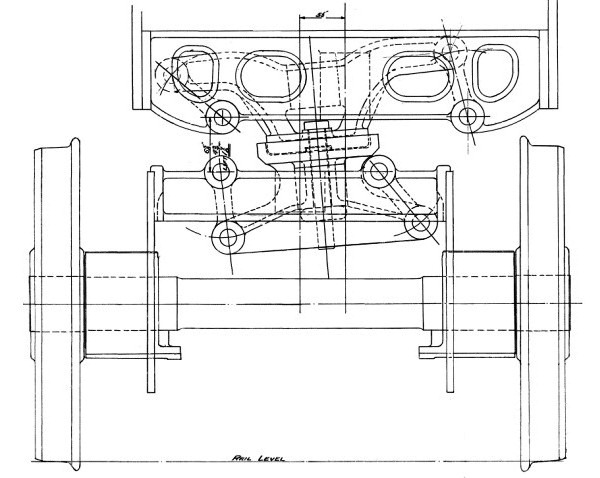
The original Gresley ‘swing link’ arrangement

As the virtual locomotive makes its way round a curve of increasing radius, so the lifting effect of the front pony truck starts to take effect. At first the suspension arrangement is able to compensate but it eventually gets to a stage where the inner wheel of the front coupled wheelset is lifted completely clear of the rail!  It would appear therefore that the modelling work already undertaken is beginning to produce results which appear convincing and point to less-than-desirable attributes which may have been behind the reputational issues of the originals.

The remaining work of the feasibility study was undertaken, based around three objectives:

1. To check whether there was any obvious reason (in terms of vehicle dynamics) why the Trust should not
proceed with the P2 project.

2. Assuming no such reason was found, to estimate the minimum curve radius that could be negotiated by the P2 as built, and how much extra lateral clearance would be required to permit operation on sharper curves.

3. To compare the behaviour of a P2 ‘as built’ to that of a P2 with a V2-style spring control pony truck.

The results of the study were submitted to the Trust by Owen Evans of DeltaRail in report ES-2013-003 at the end of February 2013. The following is a summary of the report and its findings.

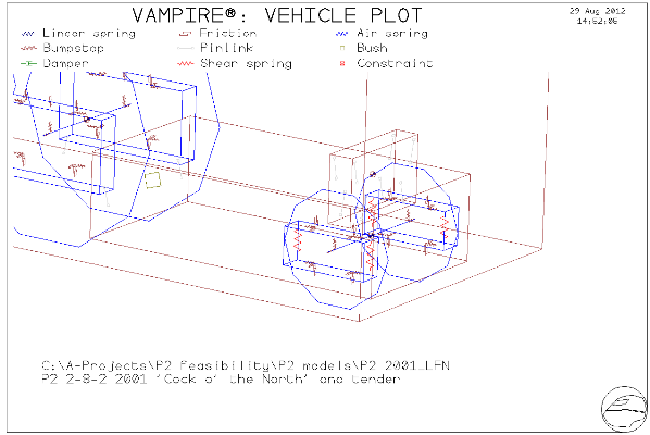
The new models of No. 2001 (‘as built’ P2) and No. 2007 (‘improved P2’ with V2-style pony truck) include some graphical information to allow much better plots to be produced than for the Tornado model.  Here is the complete ‘as built’ model, showing the suspension arrangement (below).

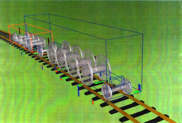
The first simulations carried out with these models was to run them round an ‘assault course’ of smooth, sharply curved sections of track. This begins with a straight, then increasing curvature to a 6 chains radius curve, followed by a further increase to 4.5 chains (with a mirror arrangement back to straight). The models were run round this track at 5 mph, and results were produced for the forces between the wheels and rails, both laterally and vertically.  This simulation enables the study of the ‘track shifting’ forces; that is the total force from each wheelset that is trying to ‘straighten out’ the track. Because the coupled wheelsets are constrained to be parallel to each, they are not all aligned with the curve and have what is known as an ‘angle of attack’. In this case, not only do the wheelsets try to shift the track, they also try to spread the gauge, i.e. to force the rails apart. On gentle main line curves with good quality rail fastenings this is not too much of a problem, but in depots and sidings where curves can be much sharper there is a limit beyond which there is a real risk of derailment. There is also a link to the vertical loads on each wheel. If the lateral load (the track shifting force) builds up too much, the effect will be to push the wheel clean off the rail (ie reducing the vertical load to zero) – not a desirable result! Having explained all this, we can look at the results as Tornado, No.  2001 and No. 2007 were run round these curves.

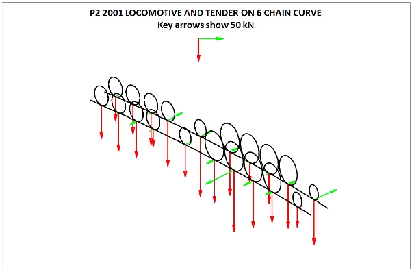
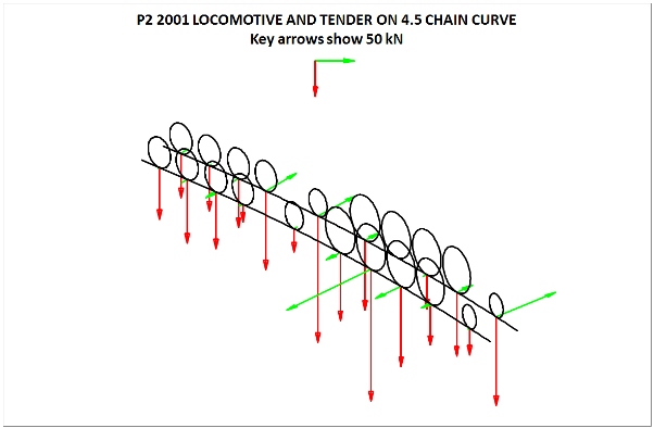
Careful study showed the greater build-up of opposing lateral (green) forces for No. 2001 and that the red (vertical) arrows on No. 2001 are quite uneven from side to side – this is most noticeable on the front pony truck.  This is quite scary- the outer wheel of the third coupled wheelset has actually lifted off the rail, and the engine is doing its very best to straighten out the curve. No. 2007 actually fared little better.  The work included a certain amount of  adjustment of hornguide clearances to achieve the best performance for No. 2007. The conclusion was that Tornado can just manage a 4.5 chain curve whereas the minimum radius that could be achieved for No. 2007 with reasonable increases in the lateral hornguide clearances will be about 5.7 chains. It was established (from the original drawings) that No. 2001 already had thin flanges on the intermediate driving wheelsets and this feature will be retained with No. 2007.

Given that such sharp curves only appear in yards and sidings, this was deemed not to be a ‘show-stopper’, so the simulations moved on to more general behaviour out on the main line. These were based around the high speed test run with Tornado between York and Newcastle on the evening of 18th November 2008. Much useful data was gathered during that test, mainly in the form of accelerations on Tornado and her tender, as well as a full speed profile for the southbound run. Courtesy of Network Rail, the measured track geometry data for the Up Fast line between Newcastle and York (as recorded by the New Measurement Train about two weeks after the test) was recovered and fed into VAMPIRE, and the Tornado model adjusted to improve its accuracy. All three models (Tornado, No. 2001 & No. 2007) could now be put through their paces over the same track data to provide a true comparison study.

A lot of information was generated, relating to ride quality, track forces and derailment risk. In some cases the P2s were better than Tornado, for example much of the ride (especially for No. 2007) and some of the track forces (remember this route is pretty straight). In some cases No. 2001 was better than No. 2007 and in others the opposite was true. Overall No. 2007 looked better than No. 2001, but would still benefit from further refinement.  One final check was ‘peak counting’. This is a somewhat complex calculation (done automatically by VAMPIRE). It looks at the lateral and vertical accelerations on the body of a rail vehicle and uses them to assess whether the vehicle is dynamically unstable. If you have ever pushed a supermarket trolley too quickly and seen the caster wheels start to vibrate rapidly from side to side, or seen a caravan snaking down the motorway, you will have witnessed dynamic instability. You can imagine that a railway vehicle behaving in this way would be quite frightening.  Additionally, lack of vertical damping means that a vehicle can build up an increasing ‘bounce’ in response to features in the track to the point where it can momentarily jump clear of the rails!

Looking at our engines, the vertical behaviour is fine for all of them, even when the section between 75 and 80 mph is analysed. This is an excellent result, borne out by the actual test results from Tornado. Looking at the lateral results, some adverse behaviour is predicted, but some of this is caused by the piston thrusts causing the engine to ‘waggle’, and this is not the same thing as dynamic instability.  Even so, only the fronts of the engines exceed the limits to any significant degree, and the P2s are generally better than Tornado (happily, this is an aspect where the longer rigid wheelbase is almost certainly an advantage!). Given that Tornado is now accepted as a mainline loco then this is an area where the comparison argument will be a likely way forward in terms of acceptance.  Overall therefore, the verdict was that the P2 project should proceed on to the design development phase (involving more detailed dynamic analysis).  Looking back, this was quite ground-breaking work, as it is almost certainly the first time that VAMPIRE has been used in this way for steam locomotives. Delta Rail completed an impressive report.

Contracts were placed with Delta Rail and Lloyds Register Rail, the former to complete the engineering studies needed to enable No. 2007 to operate on the national network and the latter the organisation that will approve the process and principles of construction. Both are critical steps. Following a meeting with Owen Evans at DeltaRail to re-start the dynamics work, wheels were drawn and added to the frame model. Crossheads, slide bars, coupling and connecting rods were also added to enable analysis of limits of increased lateral clearances on coupled wheels to permit transit of sharp curves without excessive flange scuffing.

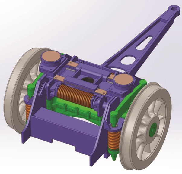
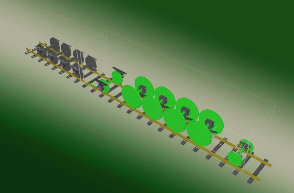
The improved V2 pony truck as applied to No. 2007

Frames

The main frames were designed in 3D Solidworks with the Cartazzi hornblocks and additional details of spring gear added to the drawing.  Materials have were specified and an order for the main frames placed with Tata Steel.  The main frame plate thickness was set at 30mm in lieu of 11/8” as was done on Tornado. A major change to address ride and reduce risk of derailment was the adoption of the post war V2 spring side control pony truck. This was drawn in 3D and has involved significant changes to the V2 design.  The order covering manufacture of the main frame and tender plates, plasma cutting, grit blasting and priming was processed by TATA and these were rolled at their Scunthorpe works 23rd April 2014 and were profiled on 21st May.

Boro’ Foundry at Stourbridge were contracted to machine the edges and drill holes in the frame plates. An order has been placed with Bakers Patterns Limited of Telford for all of the existing design frame stay and Cartazzi horn block polystyrene patterns, the castings from which were needed as soon as the frames arrived at Darlington Locomotive Works.  The 3D CAD work focused on creating a 3D model of Tornado’s diagram 118a boiler to check that mounting points on the frames are correct. Footplate brackets and running plate angles were been added to the model in order to position the holes in the frames as this is required to confirm the drilling pattern for the frames.

The decision was taken to change the manufacturing method of four of the large frame stays which provide substantial resistance to ‘racking’ of the frames – this is the tendency for one frame to try to move fore or aft relative to the other one under heavy piston forces – Tornado only has one of these!

The original components were made as steel castings. The shape and size of them precludes the use of expanded polystyrene patterns and the cost of using wooden patterns is very high as all four frame stays are different, meaning that we would only cast one off each pattern.  Compared with what was available when the P2s were first built, welding techniques have improved enormously enabling reliable fabrications to be made to replace castings. To produce high integrity fabrications full penetration welding to boiler standards is specified and the fabrication is fully stress relieved by taking it up to an elevated temperature for a period of time and then cooling it slowly. This enables the metal microstructure in the welds and surrounding areas to relax. Because the welding process involves adding metal quickly and cooling rapidly, the contraction of the welds leaves significant residual stresses in the surrounding metal which in a high fatigue environment can result in cracking. Stress relieving as the name implies releases these stresses in the structure which will give it strength and fatigue properties at least equal to and in many cases better than the equivalent casting.

Some changes to the shape of the frame stays were necessary to enable them to carry air pumps and air brake cylinders instead of the vacuum brake cylinders fitted to the original P2 class. The illustration shows the modified versions and the position of the air pumps.  David Elliott expands on the design of the frames here.

Cylinder design

Gresley’s original design for the cylinder monbloc

The cylinder block has been extensively re-designed to overcome some of the known problems with No. 2001 Cock o’ the North, principally around separation of steam and exhaust passages within the cylinder block to reduce the tendency of the incoming live steam to transfer a significant amount of heat to the outgoing exhaust steam and to minimise the clearance volume in the cylinders. The clearance volume is the space left in the steam ports and the end of the cylinder when the piston is at the end of its stroke, and which was considered excessive on the original P2 poppet valve design. Both these features reduce the efficiency of the cylinders and give rise to high coal and water consumption. We are also having to address the overall width of the cylinders to meet modern clearances with platforms, and which needs to be reduced by 2″ to give us the widest route availability. This is being achieved mostly by using higher pressure steam (250 PSI compared with the original 220 PSI) which enables the cylinder diameter to be reduced from 21″ to 19.75″. The balance of 0.75″ reduction in width is being achieved by using steel instead of cast iron for the cylinder block which permits the cylinder walls to be thinner.

Key to CAD drawings:

Turquoise – welded fabrications from plate and machined from flame cut blanks

Brown – cast valve chests and steam passages

Magenta – cylinders and steam chests from tube

Note: Illustrations 1 and 2 are of the complete block, illustration 3 has the smokebox saddle removed to enable the exhaust passages to be seen, illustration 4 shows the Kylchap double exhaust in place and illustration 5 a section through the steam passage and poppet valves.


Valve gear

The original Lentz rotary cam poppet valve gear fitted to No. 2001 Cock o’ the North had a number of problems which caused Sir Nigel Gresley to use Walschearts valve gear on the subsequent P2 locomotives and to convert No. 2001 in 1938. Our research suggests that subsequent developments with poppet valve gear would have overcome the problems experienced with No. 2001. We have choices:

1) Adopt the British Caprotti valve gear as used on No. 71000 Duke of Gloucester and a batch of BR Standard 5 locomotives

2) Improve and develop the Lentz design to overcome the shortcomings

3) If the above are impracticable, fit Walschearts gear

The use of Caprotti gear has two issues, firstly it is going to need major redesign to adapt it to the steeply inclined middle cylinder and secondly it represents a major change from the original P2 design which increases the risk of importing new unforeseen problems.

Thanks to the efforts of our researcher Andy Hardy, we have found a fair amount of correspondence between the LNER and the Associated Locomotive Engineering Company which supplied and held the rights to the Lentz gear. It would appear that the combination of the large cylinders and correspondingly large valves coupled with the small space for the cam actuating boxes on the top of the cylinders resulted in the stress levels in the drive system and cams being significantly higher than previous installations. This showed itself up on No. 2001 by rapid wear of the cams and followers, subsequently addressed by reverting to the earlier stepped cam design which had the effect of limiting the locomotive to seven steps for cut off. This did nothing to improve the already disappointing coal and water consumption for the engine!

There is little doubt that use of modern materials and heat treatments to produce extremely hard cams and followers would overcome the problem, however without extensive design and testing resources, the risk of introducing new unexpected problems is significant. Through the good offices of one of our supporters, who happened to be nearing completion of a beautiful 10 in gauge model of No. 2001 Cock o’ the North, we were introduced to George Carpenter, a locomotive engineer who worked with Chapelon and Porta and knew many of the later steam locomotive engineers including Bulleid and Stanier. George translated Chapelon’s book ‘La Locomotive a Vapeur’ which was published by Camden Miniature Services in 2000.

George’s knowledge of valve gears is encyclopaedic. He suggested that we researched Franklin type B valve gear from the USA, and produced excerpts from a book One Man’s Locomotives by Vernon Smith who was deeply involved in the development of Franklin gear and subsequently with its fitment to a number of USA locomotives during the 1940s. The Franklin Railway Supply Company’s two types of poppet valve gear (‘A’ and ‘B’) were derived from Lentz oscillating and rotary cam gears respectively and in the case of the type ‘B’ rotary cam gear, used infinitely variable scroll cams throughout. Further development work improved the other weak points of the Lentz design.

The USA does not have a central national railway museum like our NRM, and research for drawings and information is more difficult. Fortunately George Carpenter knew Vernon Smith and was aware that his son Charles had some of Vernon’s archives including details of Vernon’s work in fitting the Santa Fe 4-8-4 locomotive No. 3752 with Franklin ‘B’ gear (see photo). Charles, who amongst other things is a railway artist, proved to be most helpful lending us some drawings and two Franklin manuals for the type ‘B’ valve gear fitted to No. 3752. This gave us enough information to carry out detailed design of the valve gear and cylinders for No. 2007. Scanning the drawings was slightly problematical as the largest one is eleven feet long! Our local scanner could only cope with 8’ long drawings, so the drawings were scanned by passing them through from both ends to produce two partial scans which were subsequently been recombined electronically.

Wheelsets, axles and running gear

One of the problems experienced with the original P2 locomotives was fracture of crank axles. We are aware of at least four and possibly five occasions when a crank axle broke immediately behind the wheel. Whilst such occurrences were not uncommon in the days before routine non-destructive testing of axles by ultrasonic and more recently magnetic particle inspection, for so many events on a small class of six locomotives over an eight year period is exceptional and will not be tolerated on today’s railway.

The design of the P2 crank axle is essentially the same as that for the contemporary A3 Pacifics which were not prone to axle failure. The P2’s larger cylinders would have resulted in higher maximum piston forces and hence torque in the axle, and whilst a Pacific at high axle torque will slip dissipating the torque, the additional pair of coupled wheels on the P2s made them one of the most sure footed locomotives ever built.  Hence higher sustained torques were possible.  The fact that all these failures took place at low speed when the locomotives were accelerating hard had the fortunate consequence that none of the failures resulted in derailment.

Photo courtesy of Graham Werrett

The photo shows the failure of the crank axle on No. 2005 Thane of Fife at Stonehaven in July 1939, indicating that a crack started from the sharp corner in the end of the keyway for the key that locates the wheel on the axle. The crack had grown slowly until it was about two thirds of the way through the axle when it failed completely.

The crank axle on Tornado has several significant design improvements developed by the Timken company including a better keyway design and a stress relief groove, the surface of which was rolled to compress the material. These features enhanced the fatigue resistance by at least 60%, further improved by incorporating the BR BASS 504 wheel/axle design techniques.  A Finite Element Analysis study of the P2 crank axle undertaken by Mott MacDonald at Derby demonstrated that while our improved Timken based design was significantly better than the original, there was not a sufficiently comfortable margin of strength.  Mott MacDonald were asked to re-run the study with the axle with the bearings increased in diameter from 9.625″ to 10″ (Timken can supply bearings of this diameter which will still fit in our axleboxes) and this was the final design solution chosen.  The updated FEA study by Mott McDonald showed the improvement in fatigue lives for the worst scenarios with the increased axle diameter and modified key ways was dramatic (in the order of a factor of at least 10) leading to the conclusion that the Trust will have little difficulty in demonstrating the minimum component life of a quarter of a million miles. Given the increased power of the P2 design and the problems found with the crank axle, there was also a desire to improve the material for the sweeps. Somers Forge proposed a stronger material which retained the toughness of the original EN8 steel and this was duly approved.  You can watch the fitting of the wheels to the axles at South Devon Railway Engineering here.

The improved crank axle for No. 2007 – David Elliott